Bipolar v2 Build for Rocket City Robot Assault 2004
The Design Changes
First, I must admit I have almost no pictures of this build. So it's all me droning on and on...
Well, after a pretty abysmal showing at my first competition I had a bunch of new ideas and
I wanted to try them out. The ideas started, as most do, by observing other people's bots. Dad and I saw a couple
of full body spinners at motorama: RamByte
and Neotier. Of these RamByte was most impressive because it was
60 pounds and built by the Robotic Death Company. You may
recognize their bot Megabyte from all of the awesome youtube videos. Rambyte was just the lightweight
version and it was seriously awesome in person. I couldn't implement my weapon the way they did because
I had the two different weapon motors that were too high speed to get good gearing through belts. The
belts I was using had been nothing but trouble so I was looking for a different solution.
Neotier on the other hand was a 12 pound bot that was pitted near me. It was especially interesting because
the weapon was powered in a way I had never seen before. The builder had four weapon motors arranged
around the baseplate, each with a wheel attached to it. The wheels rolled a ring on the inside of the shell that
made the whole thing rotate. This was interesting to me because I had two weapon motors and it looked like
a really good way to get the gear ratio required for such high rpm motors.
Dad and I discussed it in great detail on the way home from motorama because going to the friction drive
would more or less require us to do what he called a "cake shell" because it was cylindrical instead of
domed. I really liked the domed shell because it would deflect blows, but agreed that the current one
was too big to actually do that because it had to be so thin from the weight. We decided that going to
a much smaller cylindrical shell would pay off by allowing it to be much thicker and giving us the friction
drive that would allow it to actually spin up.
When we got home I started to redesign the baseplate to fit into a smaller cylindrical shell. I was still
using graph paper but had a better idea of how the parts had to go together to fit. One design goal was
to get the second drive battery pack reinstalled and make weight. To do that we decided to switch to an
aluminum shell instead of a steel one. This would let us use more than 2.5 times as much material but would
require the teeth to be separate bolt-on parts. Some would say that is a bonus because it makes them replaceable
when they get banged up but I've been very happy with many expendable smaller teeth that are welded on instead.
At the competition I had seen better ways to mount some of the components as well, like the RDC guys mounted their batteries
with stainless steel pipe clamps. Because of that, in this design I planned
to use zipties to hold the batteries in. I got some ridiculously monstrous zipties from
Mcmaster-Carr and planned to mount the big weapon battery with those. I was just going to use several standard
sized zipties to hole the drive battery packs in the bot. Another significant change with this bot was to
ditch the "45 degree rotated" baseplate and let it be rectangular with two sides parallel to the wheels. I don't know
why I thought the diamond approach was a good idea in the first place but this let the baseplate get much smaller.
In hindsight it must have been really hard for my dad to not constantly point out how wrong some of my choices obviously were.
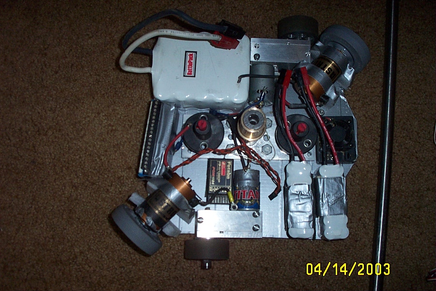
While the final layout was a little different, I was able to drastically improve the compactness of
the baseplate. This picture shows that I moved the power switches
to the center of the bot and stood the vantec speed controller up on its end. You can see it at the left of the picture
with all the tiny screw terminals on top. The final layout had the vantec moved between the drive batteries and the drive
motor on the bottom of the picture. Again, the camera date is off by a year - this was actually 4/14/2004 - after Motorama
2004. You can also see the foam mockups of the bottoms of the weapon motor mounts in this picture. The aluminum ones were
much sturdier. What you can't see in this picture is the fact that I changed all of the hardware out to hex heads but left
the slotted-drive screws threaded into the top of the drive motors so I didn't lose them. These heads were a significant
improvement over the miscelaneous hardware I had in the other version of the bot. I was very impressed with how much
better thought-out it was. Heh, still pretty bad, but lightyears ahead of where it was.
You may notice the notched extension for the thor speed controller sticking out from the standard 11 x 11 rectangle.
This was mostly made possible by my dad's jigsaw. We never used it on the first build because it didn't work. I
guess that's a pretty good reason, but now that I had all of my fancy electronics skills I decided to try to fix it.
I took the case apart and noticed that one of the motor leads had vibrated off of the tab on the motor. Once I reattached
it the jigsaw worked like a champ (and is still working today). This allowed me to cut slightly more complex shapes
than the circular saw, although I didn't realize yet that it could do curves even in aluminum. It was one small
victory that enabled the build to continue.
The Weapon System
In this bot I was completely revamping the way the weapon was powered. I was dropping the belts and central pulley
in favor of a friction driven setup with wheels on both motors. This meant I would lay the motors down and allow the
entire bot to be much shorter. Laying the motors down required completely different mounts because they now had to
be on the edge of the baseplate and not integrated with the weapon shaft mount. I ordered a gigantic block of UHMW
plastic that was 1.5" x 3" x 24" from mcmaster and some silicone adhesive-backed rubber. The plan was to use a holesaw
to cut out a hole through a block of the stuff that I could put a motor in. The hole would be lined with rubber and the
motor would be pressed through the rubber and stick out the front of the mount. I did some tests to see if wood screws
into the UHMW would be strong enough. My tests showed that the screw broke before it pulled out of the plastic so
I moved on to making the mounts.
We used a circular saw to cut off a 2.5" chunk of the big bar, then I used a small benchtop drill press to core them out.
I'd never used a holesaw before so I didn't realize how much of a problem the chip removal would be. I had to stop
three times on each piece to let the motor cool off before I got all the way through the 1.5" thickness. When I eventually
got them cored out I lined the holes with rubber than pushed the motors through to make a nice snug fit. They were extremely
tight so I was sure they wouldn't come out. I was sure about a lot of bad ideas up to this point, why not one more?
I did the same thing to the other motor and then it was time to get the weapon wheels worked out.
The weapon wheels were just colson wheels from The
Robot Marketplace, where I got almost everything but the mcmaster order. I planned to use TranTorque keyless bushings
to mount them to the motors because the set screws I used at Motorama for the roller-pulleys were another point of failure
and pain. The Keyless bushings go onto the shaft and into the bore you are mounting to it. You then tighten the bushing
down and it simultaneously expands the outside and contracts the inside to make a super-tight bond between the shaft and
wheel. The only downside is that if you are rotating the wrong direction you can sometimes loosen them with shock loading.
I didn't realize this but was fortunate enough to accidentally be spinning the right way to avoid it.
While the trantorques were an improvement over the set screws the presented a couple of problems. One problem was that
the wheels were a 39/64 bore, not a 5/8 (.625") bore so I needed to drill them out somehow. The other problem is the
trantorques were $35 apiece so I only bot the two I needed. The first problem was mostly difficult because I didn't have
a 5/8" twist-drill, only a 5/8" paddle bit. While the plastic wasn't too tough for the paddle bit, keeping them even close
to concentric was tricky. I lined them up by chucking a smaller drill bit in the drill press and using the small bushing
that came along with the wheel to reduce the bore to the size of the drill bit. I lined it all up that way, then clamped
everything down. After it was all rigidly clamped I switched drill bits and tried to carefully drill them out.
It worked and I was able to make the two wheels pretty decently. If I had to do it now I'd just chuck them in my lathe
and core them out to whatever size I needed.
The Shell
The shell on this bot was to be a complete overhaul. The wok shell looked pretty cool before I drilled all those holes
in it but it was overweight, weak, and not rigid enough. It's probably good that it never spun because the bot would have
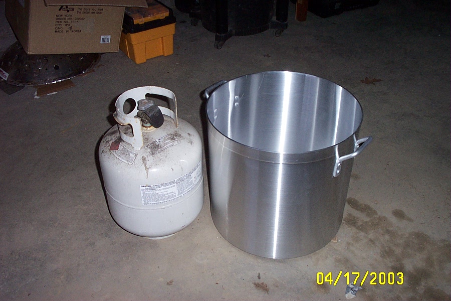
almost definitely eaten itself. This shell was going to be much smoother, a little lighter, and much more compact. I ended
up using a giant aluminum cooking pot that I sliced up to make into
the right sized shell. The best size I could find for our baseplate size was 17.5" diameter
and turned out to be 60 quarts. The baseplate was around 11" x 11" so it came out to about 15.5" corner-to-corner. This gave
a 1" air gap between the shell and the bot - much better than the old version.
Dad and I drew parallel lines at 1" intervals all the way up the side of the shell and cut them out with the jigsaw that
I had fixed. These strips were intended to wrap around the bottom of the now-3"-tall shell to make it much stiffer.
At first we were going to just epoxy them on but decided to call around and see if anybody locally could weld them on
instead. We found a place and so decided to wait until the rest of the shell was almost ready. I managed to con the
school shop teacher into letting me roll a 1" wide strip of .25" thick 6061 into a circle so we used that as the
major stiffening band at the bottom.
About one week before the competition we took the shell pieces down to a local machine shop and had the guy weld
it up. He did a pretty good job. We told him about our thoughts of using epoxy to hold it together and then
welding it for good measure and said he was glad we didn't because it probably would have messed up the welding. I didn't
tell him that he was really welding 3003 and 6061 aluminum together for most of it.
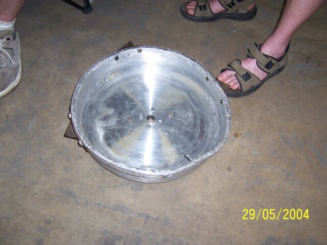
After we got it back from him I
added the bolt holes for the four teeth and attached them with big 3/8" hex bolts. I was terrified of weight because
the previous version had been so obese, so I cut down the steel bands that the teeth were welded to. As you can see
in this shot from the competition - the shell deformed on impact, in part because the force wasn't distributed as
far as it should have been. It turns out that 3003 aluminum really was as soft as everybody on the forum said.
The bearing block on the top of the shell was my first foray into both bronze bushings and lathe work. I was taking
a metal shop class at the school and decided that I would try to turn a circular bearing block. You can kind of see
the bearing block in this picture.
It was a flanged piece of
round bar with a 1.25" bore and four 1/4-20 tapped holes in it. I drilled a hole in the top of the shell with a holesaw
and tried to get the bearing block as close to the center as possible. It was made a little easier by looking carefully
at the concentric circle marks in the aluminum finish of the pot. The four grade-2 hex bolts I used to hold it onto
the shell were probably not strong enough, but they weren't the first failure point. I didn't use a boring bar to carve
out the bearing hole, instead I used a 1.25" twist drill. Naturally the hole was oversized so the bearing fit in very
loosely.
The Assembly
There are a few different design choices I made in this bot that were improvements over the previoius version.
The first was to pick a standard hardware type. The drive gearboxes use three #10-32 screws apiece to hold them
on the baseplate. Because of this I attempted to standardize on 3/8" long #10-32 hex head machine screws for as
many of the parts as possible. The previous version just used whatever hardware my dad had laying around. For
this version I actually ordered in a box of 50 of these screws. Unfortunately, the only holes that could possibly
be #10's were the drive motors.
I also just found out about zipties. Because they are fast and disposable I decided to use them for the parts that
had to be removed from the bot often. Those parts were the batteries, which unfortunately also got hot and were
the heaviest parts in the machine. This time I coated the whole baseplate in duct tape instead of a miller light
box to isolate it. This was much easier to work with but still probably unnecessary.
The wiring this time was not as random. I was a little more prepared when I started the wiring and actually drew
out where each of the wires had to go and made them the right length. I tried to run solder on as many of the connectors
as possible but it was hard for me to be patient enough for my little 30 watt radio shack soldering gun to add enough heat.
In the end I was pretty satisfied with the way that part worked out, though I didn't realize yet that I should use something
to keep any press-fits together and that ended up biting me at the event.
Once I got the whole bot together I tried to power everything up without the shell on. The drive system seemed to work
ok despite the wheels being offset from eachother. Unfortunately, the weapon motors didn't spin up. I double and tripple
checked the wiring but everything looked ok. I also messed around with the ThorSC PWM cable to see if I had it plugged
in backwards. Everything seemed ok. I emailed back and forth with Jim Smentowski at
The Robot Marketplace where I got the booster and the controller but he said there wasn't much that could go wrong
with the cables. I was still hopeful though, so I had him ship me a replacement cable. I couldn't imagine that
the controller just died while in storage. I wasn't 100% sure it was working when I put it away, but I thought so. The
belt didn't stay on the motors in the last bot for more than about 10 seconds after all...
When the cable finally arrived I plugged it in and found the same problem. The ThorSC just blinked orange - no signal.
I was so frustrated with the project that I could have just screamed. I didn't have hardly any money left after paying
the welder for the shell but the competition was coming up and I didn't want to cancel the trip because of something like this.
I overnighted a replacement thor spin controller to the house and installed it. Everything finally worked.
The Testing
We got everything working with only a couple days before leaving for the event.
I was eager to find out if the bot could spin up at all since the last one got as far as electrical functionality but
the mechanical systems were horribly flawed. On the other hand, I didn't want to end up breaking something
and cancelling our trip to Alabama. Dad and I decided to try a simple test of spinning it up without hitting anything
first and proceed from there. To my amazement, the thing spun up to a pretty scary speed. Fast enough that it concerned
me that it might hurt someone. The other one wasn't really scary at all.
After a few spinups we were feeling more confident so we decided to get a piece of wood to hit. We grabbed a log that
we were planning to split up and burn and put it in the driveway. I spun the shell up and went after the log. The shell
chewed through the soft wood and kept on spinning. I was amazed at how well it worked actually. The display so vastly
exceeded our expecations that we decided to get a little bolder. We decided to see what happened to the bot when it
tried to self-right. We put it on its back and I spun it up. The shell and base started to counter rotate and the thing
wobbled back and forth. After about 15 seconds though, something white flew out of the shell and I had to shut it down
to see what happened.
The ER - Emergency Repairs
The "something white" turned out to be shrinkwrap from the batteries. The heat from the testing combined with the
forces exerted on the battery mounts because of the baseplate spinning rapidly caused them to shift outward. The bolt
heads from the tooth bolts hit against the shifted battery packs and completely destroyed one of the drive packs. They
also peeled the shrink off of the outside of one of the cells in the weapon pack but it looked like it might be ok. I
took the packs out of the bot and did some last minute electrical-tape surgery to re-isolate the exposed weapon cell.
I ended up just leaving the drive pack at home and intended to make do with the other 5 I had.
After getting the bot all patched up and reinforcing the ziptie battery mounts with more zipties, I resolved not to try
to self-right the bot if it did get inverted. It was worth a try, and a valuable thing to know because it was easier to
recover from at home that it would be at the event. If I didn't wait till the last minute it would have been even less
scary. I packed my tools and it was off to the 22 hour drive to the Rocket City
Robot Assault