Tripolar Build for Motorama 2005
This bot was going to be the first really well thought-out bot I ever made. I actually started the build by
building a list of things that did or did not work in the old versions, and everything I had learned through
my research and experiences at two events. With that said, this was also the first bot that I took real pictures
of so the reports are going to end up with more pics and fewer words. Lucky for you :)
The name of this bot was determined by two different things. The previous two versions of my shell spinner were
both called Bipolar, so with the third version and a radical redesign, I decided to change the name of the
third version to TRIPoler. Additionally, I decided to change from using two big teeth
to using several much smaller teeth after seeing
Shrederator demolish somebody with that tooth strategy. There would now be three rings of teeth
to further enhance the TRI wording.
The Design and Parts
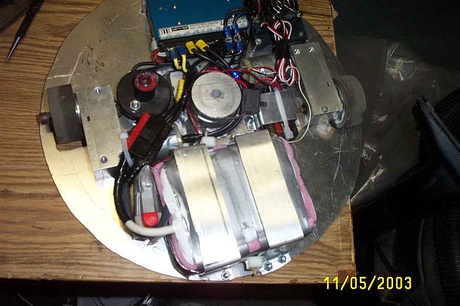
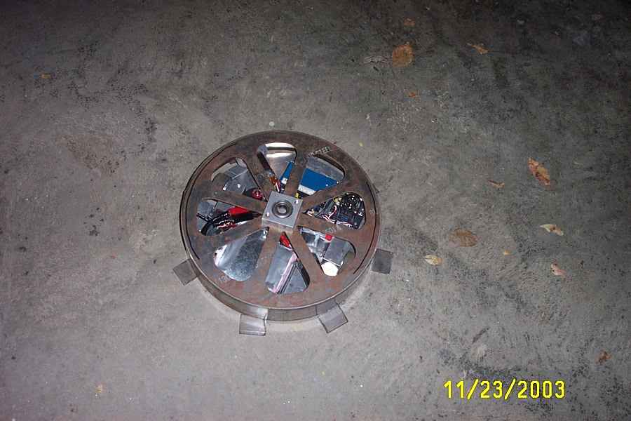
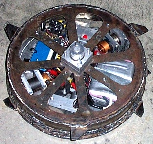
This is what the autopsy looked like from the second version of Bipolar that was now being retired. Notice the zip
tie mounts, dual power switches, strangely shaped weapon shaft mount, and rectangular base. These are all things
that I intended to change for the new version. I intended to keep the friction drive setup though because despite
the motor mounts and wheel hubs being poor, the friction system worked pretty well. Once again, the dates are messed up
The new version actually had a circular base plate because I discovered that I could cut it with a jigsaw. Until now
I tried to stick to rectangular plates so that I could cut it myself. This provided significantly improved internal
space and allowed me to make everything smaller. This base is 14.5" diameter, while the last one was 15.5" corner-to-corner.
That was a big improvement that allowed me to make a steel shell.
You may have also noticed that I removed the two 12-cell drive battery packs. I was going to replace the drive motors
with Small Johnson motors like Totally Offensive did, and run the whole thing at 24v, dual rated 50% in the transmitter.
I got the idea by talking to Robert Woodhead and reading his tutorial on how he did the conversion. This freed up almost 2 pounds of weight, and allowed
the base to shrink significantly. It also simplified the wiring by requiring only one power switch. A win all around!
The layout of this bot required a little bit forethought but was mostly facilitated by me using a copy of AutoCad Release 14.
Without it the parts likely would not have fit together and I wouldn't have been able to create the shell at all. This
was my first real foray into actual CAD work and I have to say doing without is pretty rough. I know of one successful
builder today that still does all his layouts on paper, but I don't understand why. I don't use autocad anymore
because I found a free, super simple tool that is easier to use called
eMachineShop. I highly recommend it for any 2d layout.
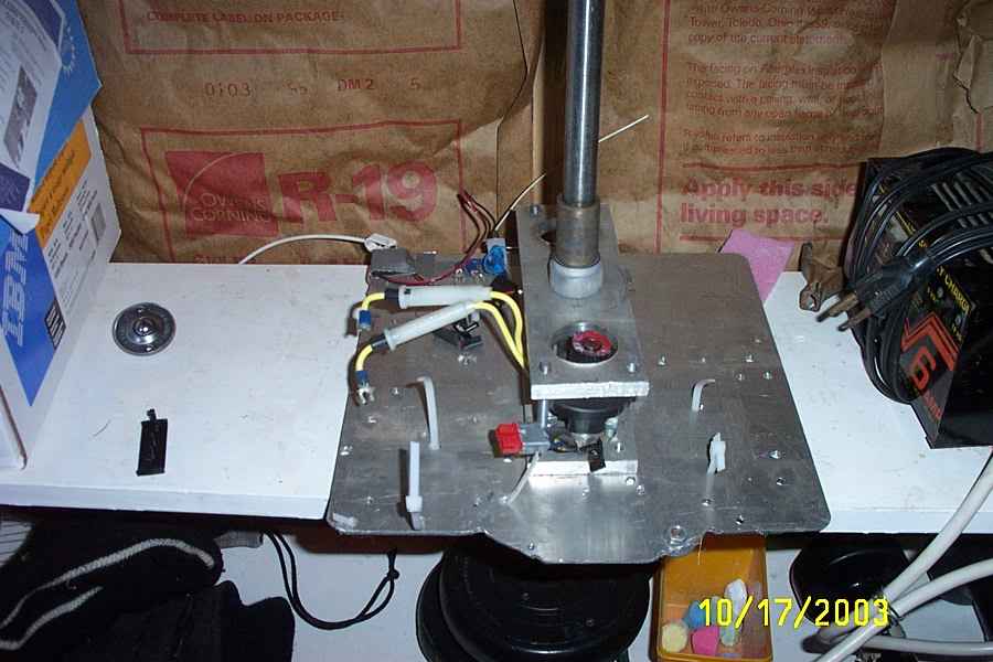
This bot was going to have a greatly improved shaft mount. The plan was to take a piece of round stock
that I had turned on the lathe at school to have a hole for the shaft, and weld it to the baseplate and shaft.
I used aluminum welding for the shell on the last version and the welds held up great. This would be a very strong
way to hold the shaft mount to the base plate that didn't require much weight. The steel shell had me really worried
about weight...
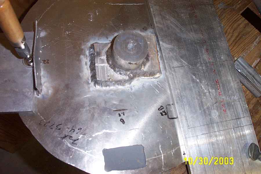
Unfortunately, welding the baseplate caused the 1/8" thick material to warp horribly. I ended up trying to clamp it and
bend it back toward flat before mounting any of the parts. You can see that the welder got the shaft mount and
Vantec mount done before realizing everything was starting to bend. The Vantec mount was the bigger offender because
it didn't have enough mass to draw the heat away from the base plate. At least the shaft mount was a big ol' block of
aluminum. The good news is that the most-warped part was the vantec side, and that was the place that didn't need
the clearance because the vantec was only 1.5" tall while the battery on the opposite side of the base plate was
2.375" tall.
The Shell
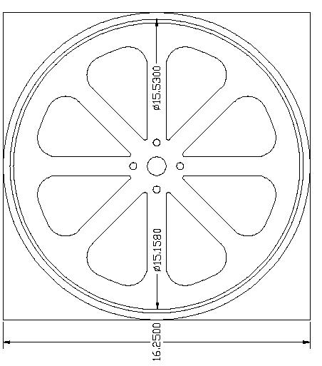
In addition to the baseplate layout, I used AutoCad to make the drawing of the new shell top. This was actually required
because I was going to do something else I had just learned about from Team O-Town: Waterjetting. My inability to make
a good shell out of cookware led me to see what it would take to make a custome one. I intended to be a simple cylinder
like Shrederator because I was so impressed with how solid it was and I had no idea how to make a conical shell. At the time
a company known as DC WaterJet was the leading waterjetter for combat robots, so I sent the material and the drawing
to them and they cut it out for me. They did a good job, but many have had trouble with tapered cuts on thicker material
from them. I recommend Team Whyachi / Westar Mfg
or Big Blue Saw for this now.
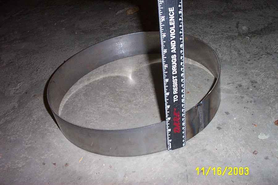
I ordered in a 4' strip of 1/8" 4130 steel from Online Metals and had a local
shop roll it into a ring for me. I think this part only cost me about $15 because it was so quick for them. I got to watch
it in person and it was cool to see the monster roller. The place makes big pressure tanks as their main business. It came
out very close to round and I was satisfied.
Here you can see what the shell looked like before I got it all welded up. I pressed the top into the ring to ensure that
it was round. It wasn't too tight to fit but it did require some negotiating. In hindsight that was a bad idea because
the pressure inward caused the top to bubble when the welding heated it up around the edge. It would have done it in
fights if it didn't happen during welding anyway, but if it was welded on top of the ring I would have had more vertical
height and clearance without the warpage. No big deal though, it still went on the bot ok.
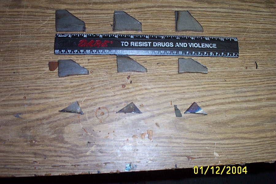
The teeth were three rows of small, angled teeth. They would be welded to the side of the shell parallel to the floor.
The backs of the teeth are clipped to remove weight, and I found out later on that it was advantagous to spin "backwards"
, meaning toward the angled faces, in order to reduce the bite and the tendency for the bot to kill itself. I cut these
teeth out of the pie-wedge shaped plates that were taken out of the top steel plate. 1/8" was pretty thin but they held
up ok because they were so short. The bottom row are shorter than the others because I added ~.25" of steel for the bottom
.75" or so to make it stiffer. This worked out much better than the original steel shell and never bent in any fight since.
The shell was designed to bolt directly on to two Team Delta Engineering
RCM220 pillow blocks. These only came with two tapped holes so I had to drill the other corners myself. You might notice in
the picture that two of the bolts have nuts on them. The only tap I had for 3/8-16 threads was a bottoming tap, and no matter how
hard I tried I couldn't get it started in the holes I made, so I just drilled them out and put nuts on them. I didn't know there
were different kinds of taps, only that I had one that didn't work. Rather than researching like I should have, I made a rash
decision to just drill them to 3/8". It didn't end up being a problem but I should have researched it.
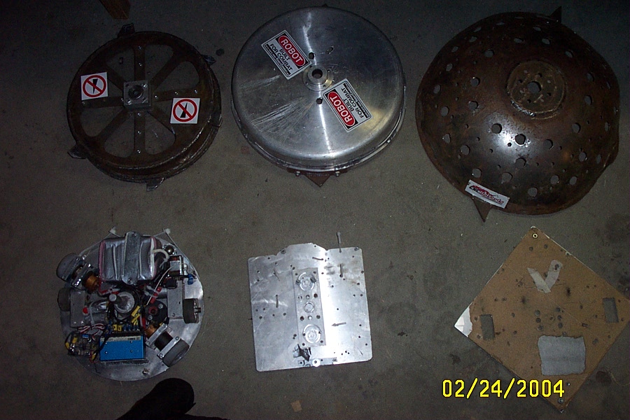
Well, there you have it, TRIPolar built with an actual cad package, a round baseplate, and a beefy steel shell. Here you
can also see the evolution of shells and baseplates from the beginning.
I managed to finish this bot more than a couple of days before the competition and did a spin test in our local fire
hall's pavilion. I needed the covered roof because there was snow everywhere in February of 2005 (imagine that!).
I tested the new bot against the aluminum shell and proved that this one was
much stronger than the old one. Check out
how the bot did at Motorama 2005.